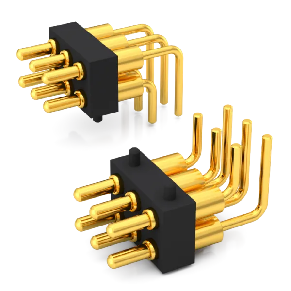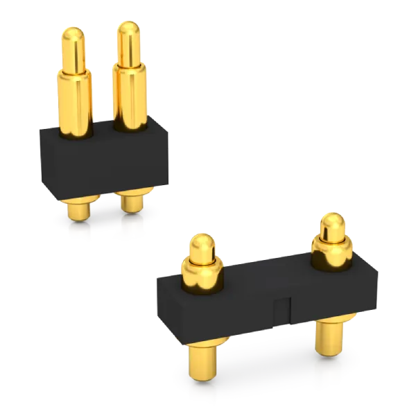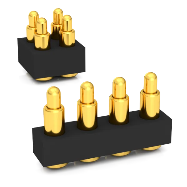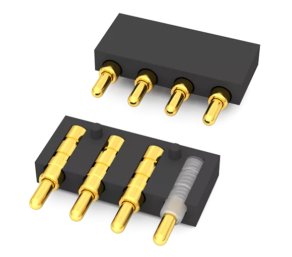
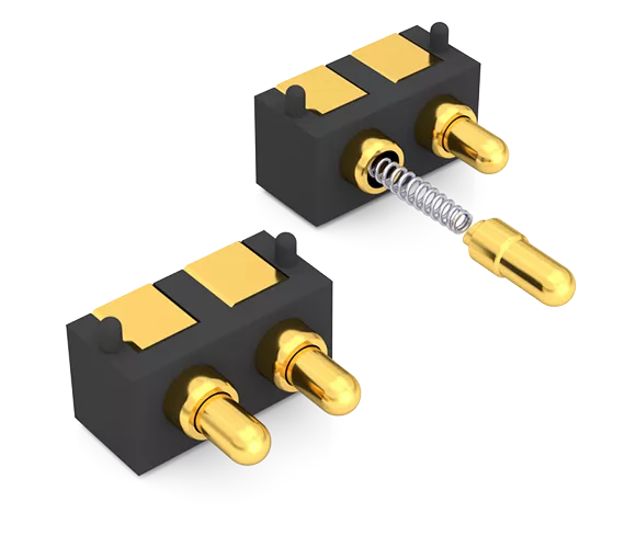
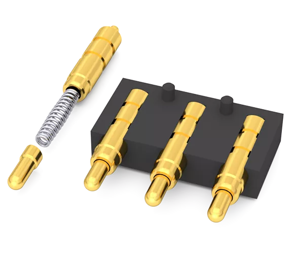
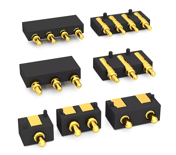
- Innovative design:Slope Structure Design,More Stable Contact, Lower Resistance
- Installation method: SMT Surface Mount (SMD) Reflow Soldering or Placement by Insertion Machine and Fixation by Wave Soldering
- Contact Resistance:30 milliohms Max.
- Rated Current:10A-30A(Continuous Current)
- Rated Voltage:36V AC/DC
- Durability:Min.10,000 Times(Reciprocating Motion Lifespan)
- Operating Temperature: -40°C to +120°C(Continuous Temperature)
- Salt Spray Resistance 96 Hours Corrosion Test
- High-Precision Mold And Parts Processing
- A variety of standards are available, and samples will be sent out as soon as the same day.
- Provide Customized Services
- Comply With EU RoHS And Reach Standards
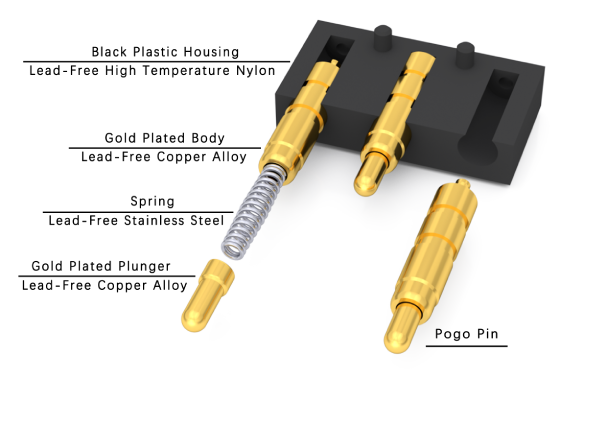
The interior of the SMD Side Contact Pogo Pin Connector adopts an inclined surface structure and built-in spring mechanism design. It is mainly composed of multiple Pogo Pins and housing, two core components, assembled through precise molds and specialized equipment. The purpose of the inclined surface structure design is to ensure that when the Pogo Pin is working, the lateral force generated by the contact between the inclined surface and the spring allows the pinhead to maintain stable contact force with the inner wall of the pin tube. This promotes the main current path through the gold-plated pinhead (Plunger) and pin tube (Body), thus achieving stable and extremely low contact resistance, maintaining stable and reliable connection even in frequent plug-ins and plug-outs.
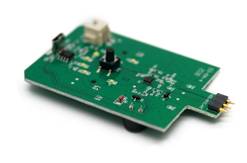
Application of SMD Side Contact Pogo Pin Connector
Installation method of SMD Side Contact Pogo Pin Connector:
SMT automatic patch reflow soldering technology: The SMT automatic patch machine automatically mounts the SMD Side Contact Pogo Pin Connector onto the PCB circuit board with printed solder paste. The solder legs are precisely inserted into the holes of the PCB circuit board, and then the solder paste is melted and solidified through the reflow soldering process, completing the fixed connection with the PCB solder pad. This process is fast, highly accurate, highly automated, significantly improving production efficiency and product quality.
SMD Side Contact Pogo Pin Connector Structural Composition
The SMD Side Contact Pogo Pin Connector is a type of Pogo Pin connector, a built-in spring connector manufactured based on an inclined surface structure design. It is typically composed of two core components, the Pogo Pin and the housing. Its characteristic is the side contact type, suitable for SMT automatic patch reflow soldering. It has high welding strength (more firmly welded with the PCB circuit board), very low resistance, stable and reliable connection, long lifespan, and is more durable.
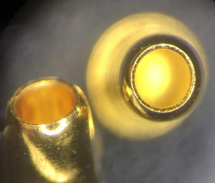
Vacuum blind hole plating technology
The vacuum blind hole electroplating technology is known for its superior performance, capable of quickly and accurately electroplating a layer of gold inside and outside extremely fine blind holes. This excellent electroplating process not only ensures the overall aesthetics of the metal surface but also has outstanding corrosion resistance and wear resistance. Both the inside and the outside of the hole present a bright golden color, and there will be no peeling or gold dropping issues.
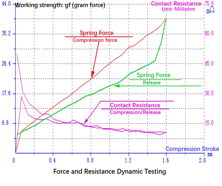
Very low and stable contact resistance
Mature design, high-precision processing and advanced vacuum blind hole plating technology are combined to achieve extremely low and stable contact resistance.
Standard product catalog
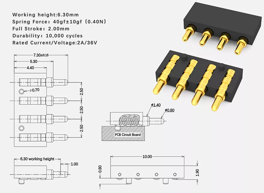
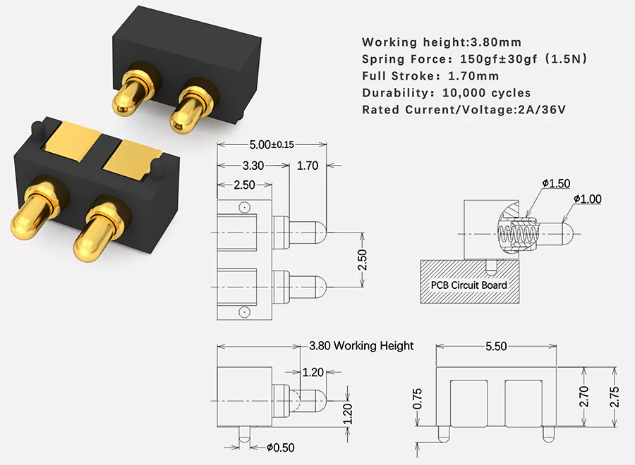
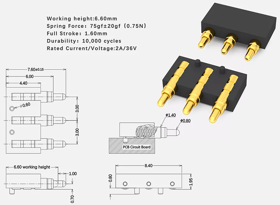
| Material: | Main Technical Parameters: |
| ● Plunger: Lead-Free Copper Alloy | ● Standard state: |
| ● Body: Lead-Free Copper Alloy | ● Operating temperature: -40~+120°C(Standard) |
| ● Spring: Stainless Steel | ● Operating humidity: 20-85%RH |
| ● SolidPin: Lead-Free Copper Alloy | ● Storage temperature: -10~+50°C |
| ●Housing: Lead-Free-High Temperature Nylon | ● Storage humidity: 20-85%RH |
| ● Rating voltage: 36V AC/DC(Standard) | |
| ● Rating current: 2A/Pin Continuous(Standard) | |
| ● Contact resistance: 30 mΩ Max.(Standard) | |
| ● Withstanding voltage: 250V AC ,1 Minute | |
| ● Insulation resistance: 500 MΩ Min. | |
| ● Durability:10,000 Cycle(Standard) | |
| ● Working Spring Force:70~180gf(Standard) | |
| Electroplating: | Contact Type: |
| ● Plunger: Ni Plating 1.4μm, Gold Plating 0.30μm | ● Vertical Contact Type |
| ● Body: Ni Plating 1.4μm, Gold Plating 0.10μm | |
| ● SolidPin: Ni Plating 1.4μm, Gold Plating 0.10μm | |
| Installation Method: | Environmental Protection Standard : |
| ● SMT automatic placement machine+Reflow soldering | ● Comply with EU RoHS and Reach standards |
| ● Plugin machine + Wave soldering |
| SN | Product Image | Number Of Pins | Pitch | Catalog Download |
| 1 |  | 2Pin | 2.50 | 2Pin-Pitch2.50-SMD Side Contact Pogo Pin Connector |
| 2 |  | 3Pin | 3.00 | 3Pin-Pitch3.00-SMD Side Contact Pogo Pin Connector |
| 3 | 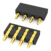 | 4Pin | 2.50 | 4Pin-Pitch2.50-SMD Side Contact Pogo Pin Connector |


