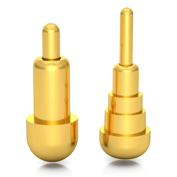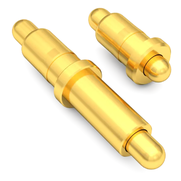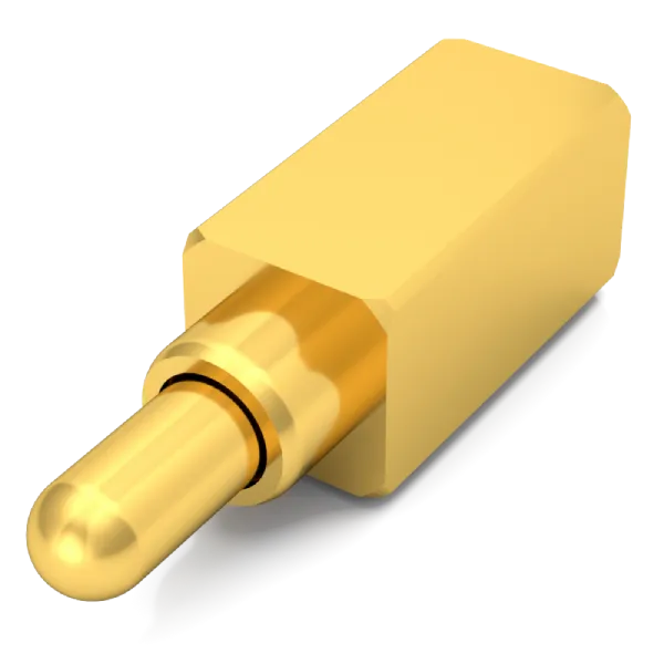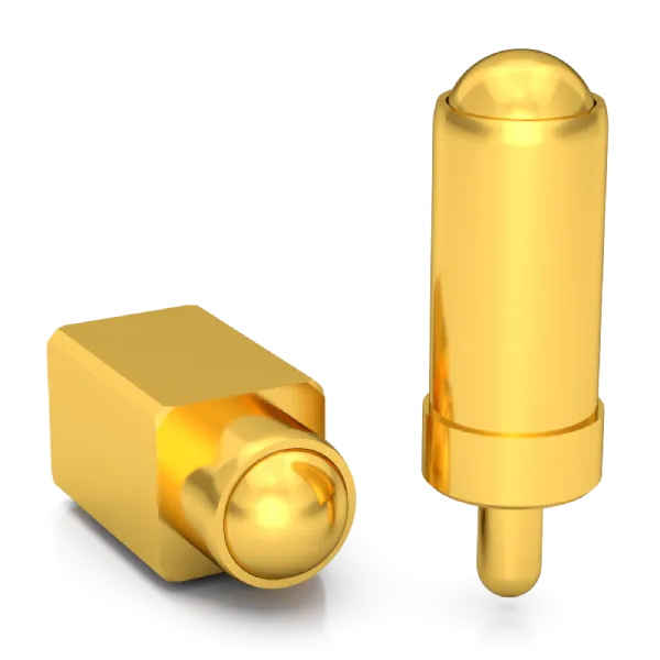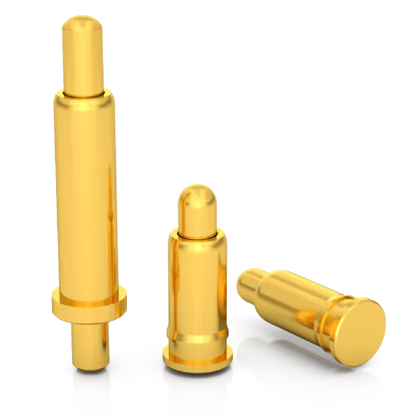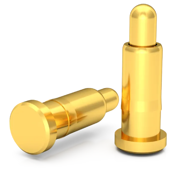
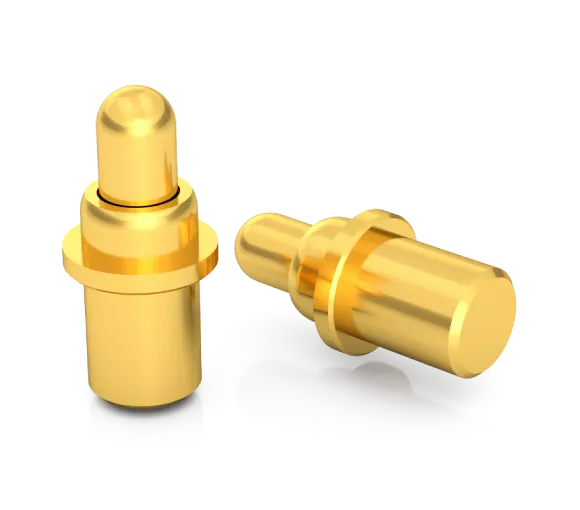

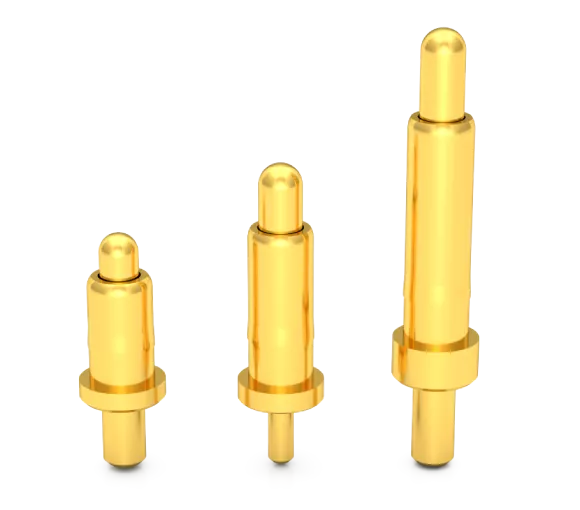
- Innovative design:Slope Structure Design,More Stable Contact, Lower Resistance
- Installation method: SMT Surface Mount (SMD) Reflow Soldering or Placement by Insertion Machine and Fixation by Wave Soldering
- Contact Resistance:30 milliohms Max.
- Rated Current:10A-30A(Continuous Current)
- Rated Voltage:36V AC/DC
- Durability:Min.10,000 Times(Reciprocating Motion Lifespan)
- Operating Temperature: -40°C to +120°C(Continuous Temperature)
- Salt Spray Resistance 96 Hours Corrosion Test
- High-Precision Mold And Parts Processing
- A variety of standards are available, and samples will be sent out as soon as the same day.
- Provide Customized Services
- Comply With EU RoHS And Reach Standards
Dip Pogo Pins are designed with a bevel structure and built-in spring mechanism. They are mainly composed of three core components: Plunger, Spring and Body, and are assembled through precision molds and special equipment. The function of the bevel structure design is to ensure that when the Pogo Pins are working, the lateral force generated by the contact between the bevel and the spring is used to maintain a stable contact force between the needle and the inner wall of the needle tube, prompting the current path to mainly pass through the gold-plated needle (Plunger) and needle tube ( Body), resulting in stable and extremely low contact resistance, maintaining a stable and reliable connection even during frequent plugging and unplugging.
How to install DIP Pogo Pins:
SMT automatic patch reflow technology: The SMT automatic patch machine automatically mounts DIP Pogo Pins onto the PCB circuit board with solder paste printed on it. The solder pins are accurately inserted into the PCB circuit board holes, and then the solder paste is melted and soldered through the reflow soldering process. Curing to complete the fixed connection with the PCB pad. This process is fast, highly precise and highly automated, greatly improving production efficiency and product quality.
Plug-in machine + wave soldering technology: The automatic plug-in machine automatically mounts DIP Pogo Pins and accurately inserts the solder pins into the PCB circuit board with printed solder paste, and then melts and fixes the solder paste through the wave soldering process to complete the soldering process with the PCB pad fixed connection. The process is fast, accurate and highly automated, greatly improving production efficiency and product quality. Suitable for electronic components with extremely long solder legs that cannot be fixed through SMD reflow soldering

Materials and parts composition
DIP Pogo Pins is a classification of Pogo Pin connectors. It is a built-in spring connector designed and manufactured based on the bevel structure. It usually consists of three core parts: plunger, spring and body. It is characterized by its own soldering feet and precise positioning. , high welding strength (stronger welding with PCB circuit board), low resistance, stable and reliable connection, long life and more durable.
Three internal structures
There are three commonly used internal structures of Rtench’s Dip Pogo Pins, namely Plunger bevel structure, Plunger bevel + steel ball structure and Plunger inner hole bevel structure.
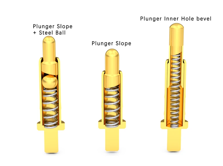

Internal structure current path
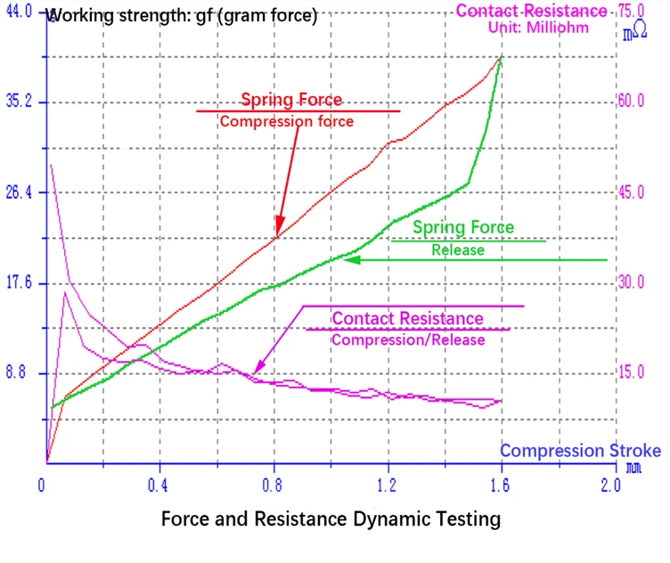
Contact force and contact resistance are the core factors for stable and reliable connections, and there is a direct relationship between contact force and contact resistance. Increasing contact force can effectively reduce contact resistance. Therefore, achieving stable contact force and contact resistance is key to establishing a reliable connection.
When the bevel and spring are working, the lateral force generated is converted into contact force, allowing the gold-plated needle to maintain stable contact with the inner wall of the needle tube, thereby obtaining stable and extremely low contact resistance, ensuring a stable and reliable connection.
Pogo Pin Surface Treatment
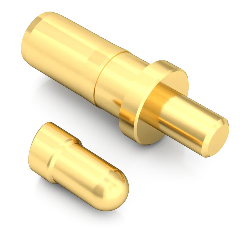
Before Electroplating
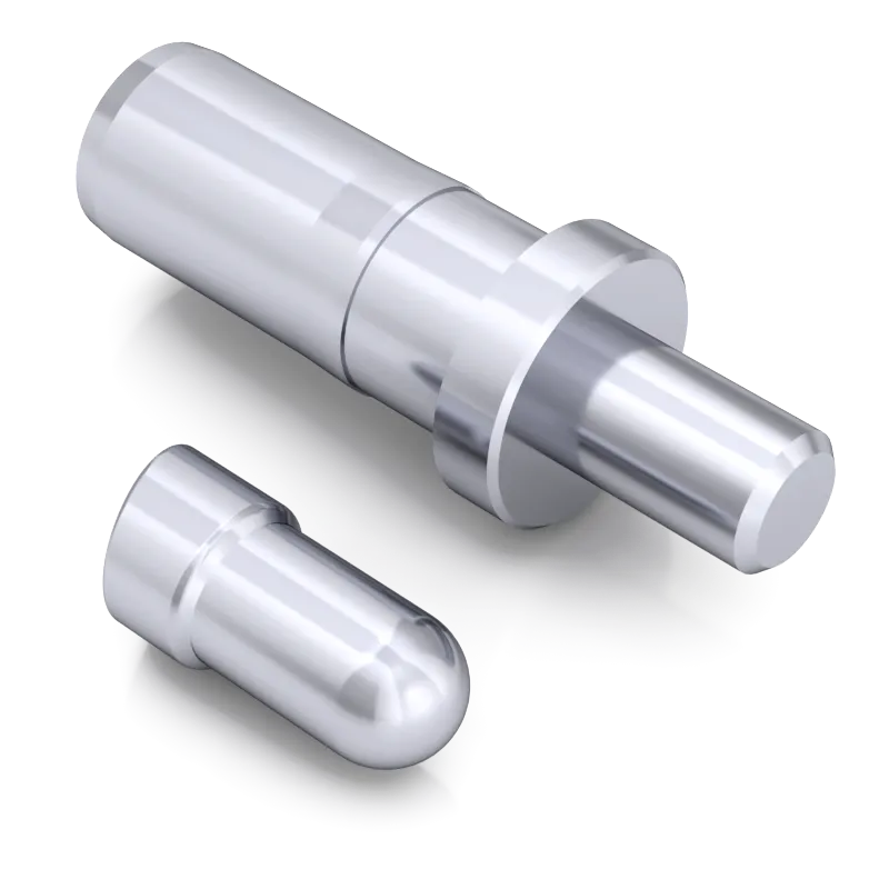
Electroplated Nickel
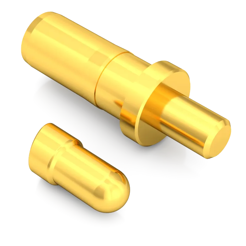
Electroplated Gold
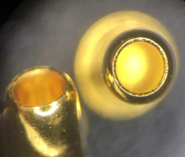
Vacuum blind hole plating technology
Vacuum blind hole plating technology is known for its excellent performance and can accurately plate a layer of gold inside and outside extremely fine blind holes. This advanced electroplating process not only ensures the overall beauty of the metal surface, but also provides excellent corrosion and wear resistance. Every detail, whether inside or outside the hole, shows a golden and shiny color, and there will be no peeling or gold falling off problems. The precision and stability of this technology ensure the durability and durability of the electroplated layer, meeting a variety of demanding application requirements.
Very low and stable contact resistance
Mature design, high-precision processing and advanced vacuum blind hole plating technology are combined to achieve extremely low and stable contact resistance.
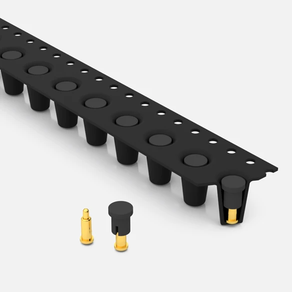
Packing

Standard product catalog
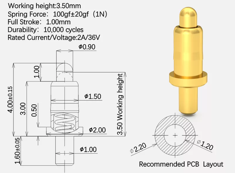
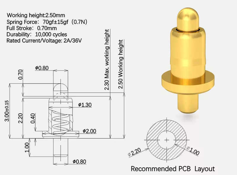
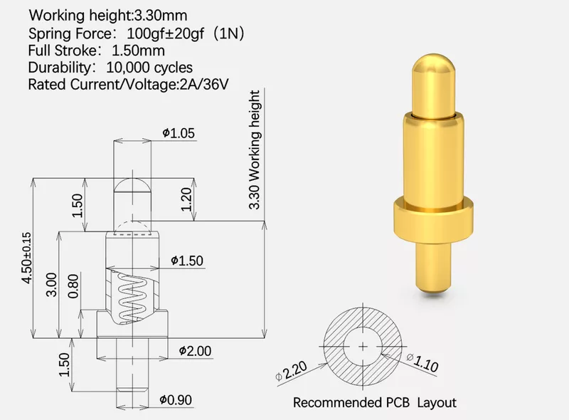
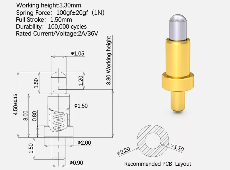
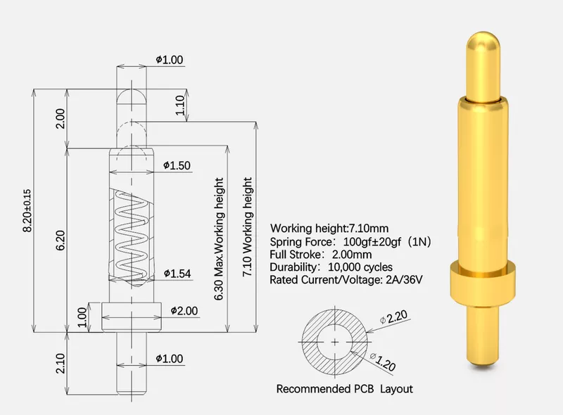
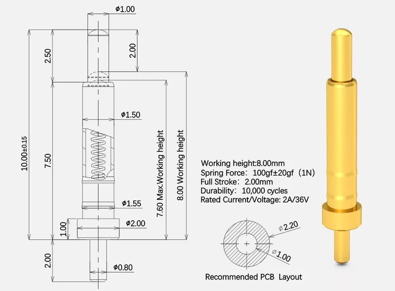
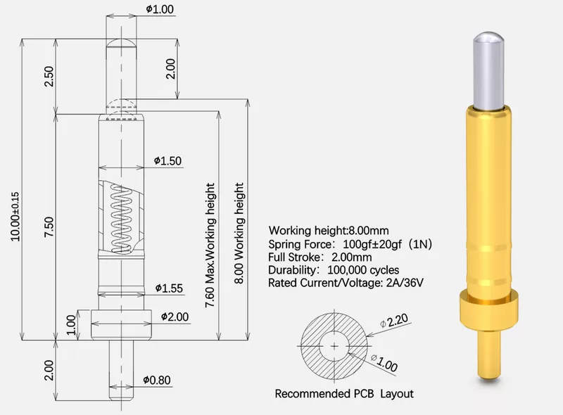


| Material: | Main Technical Parameters: |
| ● Plunger: Lead-Free Copper Alloy | ● Standard state: |
| ● Body: Lead-Free Copper Alloy | ● Operating temperature: -40~+120°C(Standard) |
| ● Spring: Stainless Steel | ● Operating humidity: 20-85%RH |
| ● SolidPin: Lead-Free Copper Alloy | ● Storage temperature: -10~+50°C |
| ● Storage humidity: 20-85%RH | |
| ● Rating voltage: 36V AC/DC(Standard) | |
| ● Rating current: 2A/Pin Continuous(Standard) | |
| ● Contact resistance: 30 mΩ Max.(Standard) | |
| ● Withstanding voltage: 250V AC ,1 Minute | |
| ● Insulation resistance: 500 MΩ Min. | |
| ● Durability:10,000 Cycle(Standard) | |
| ● Working Spring Force:40~120gf(Standard) | |
| Electroplating: | Contact Type: |
| ● Plunger: Ni Plating 1.4μm, Gold Plating 0.30μm | ● Vertical Contact Type |
| ● Body: Ni Plating 1.4μm, Gold Plating 0.10μm | |
| ● SolidPin: Ni Plating 1.4μm, Gold Plating 0.10μm | |
| Installation Method: | Environmental Protection Standard : |
| ● SMT automatic placement machine+Reflow soldering | ● Comply with EU RoHS and Reach standards |
| ● Plugin machine + Wave soldering |
| SN | Product Image | full stroke | Initial Height | Working Height | Catalog Download |
| 1 |  | 0.4~0.8 | 1.80~3.00 | 1.40~2.60 | short-Dip Pogo Pins |
| 2 |  | 1.00 | 3.15~6.30 | 1.50~5.60 | 1.00-Dip Pogo Pins |
| 3 |  | 1.50 | 4.50~10.00 | 3.20~9.00 | 1.50-Dip Pogo Pins |
| 4 | 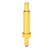 | 2.00 | 5.80~16.00 | 4.00~15.00 | 2.00-Dip Pogo Pins |
| 5 |  | 2.50 | 7.10~16.00 | 4.80~15.00 | 2.50-Dip Pogo Pins |
| 6 | 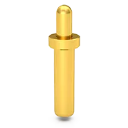 | 3.00 | 8.40~20.00 | 5.60~19.00 | 3.00-Dip Pogo Pins |
| 7 |  | 3.50~5.00 | 9.70~20.00 | 6.40~19.00 | 5.00-Dip Pogo Pins |


